Networking Refactor: Turning my HomeLab into a Zero-Trust environment
Let’s face it: the current networking state of my homelab is an absolute mess. If a threat actor were to find a way into one of my VMs, it would be trivial for them to try and gain access to the rest of the network.
Given that my HomeLab shares a LAN with non-tech enthusiasts, it is of uttermost priority to try and keep an airtight security in the network. We don’t want vulnerable data to be exposed due to unsecured network shares, right?
Our lord and savior: A Zero-Trust Network
Zero Trust is a security model where the core architecture assumes no entity, inside or outside the network, is trustworthy by default and requires strict verification.
Cloudflare.com: “Zero Trust security | What is a Zero Trust network?”
By following this model, we assume that a threat actor will eventually succeed in compromising a service in the network. In this age of AI-powered vulnerability research and constant supply chain attacks, I fully understand why such a mindset is needed.
The question that this security model answers is “What do we do to lessen the impact?”.
Applying Zero Trust to the HomeLab
The Zero Trust security model includes establishing MFA (Multi-Factor Auth) and other features, but this attempt will be limited to the Networking side of things.
With out main objective being to limit lateral movement to the attacker, I created the following structure for my network:
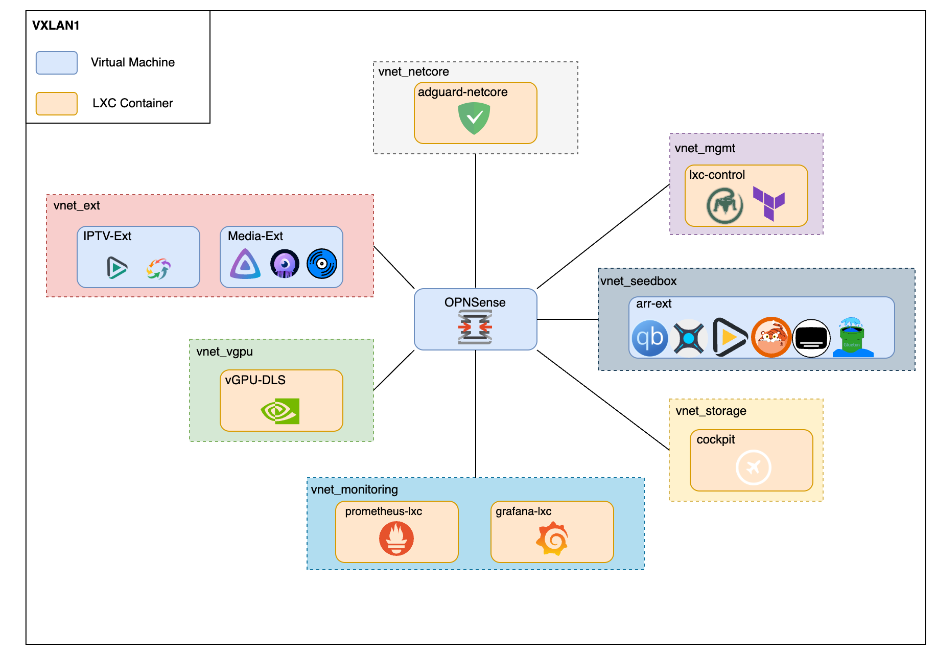 Segmentation of virtual machines using VLANs
On the top-left corner you can see that the biggest block in the hierarchy is called “VXLAN1”. This is because currently I am using Proxmox’s SDN (Software Defined Networks). This allows me to use the same shared bridge on the vNICs that belong to VMs in different nodes of the cluster.
If you’re in a single PVE node and not using SDNs, same thing can be accomplished via Linux Bridges instead of VNets.
Creating the Virtual Networks
First and foremost, we need to create the Virtual Networks. When using Proxmox SDNs, you do this via the Datacenter -> SDN -> Vnets view.
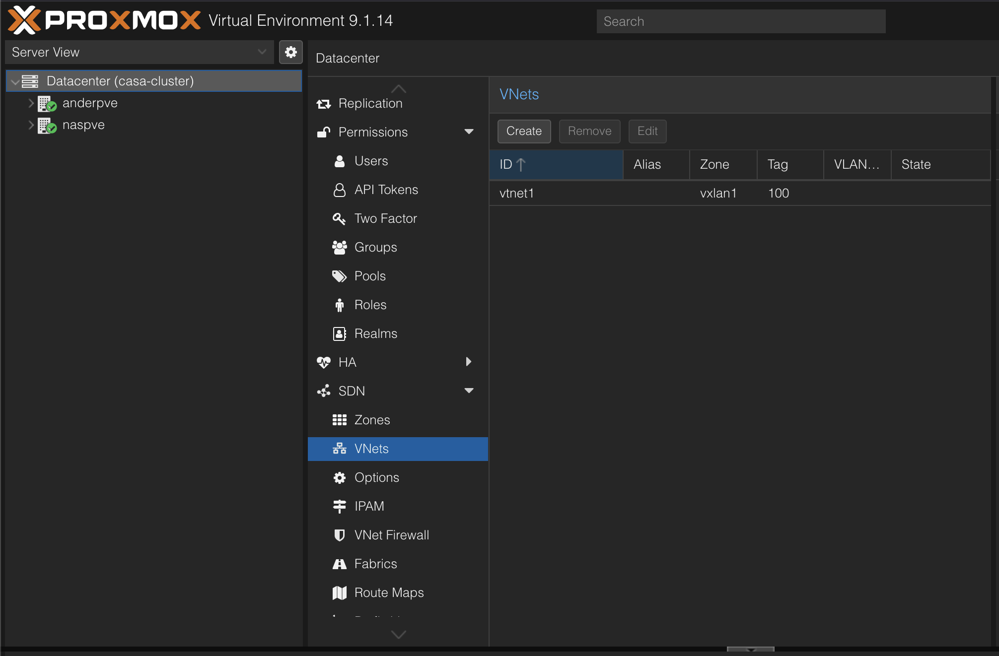 Network View when using SDNs in Proxmox
Next step is to create a Virtual Network for each isolated VLAN that we want. Since we are relying on Proxmox for traffic tagging and management, we do not need to enable the “VLAN Aware feature”.
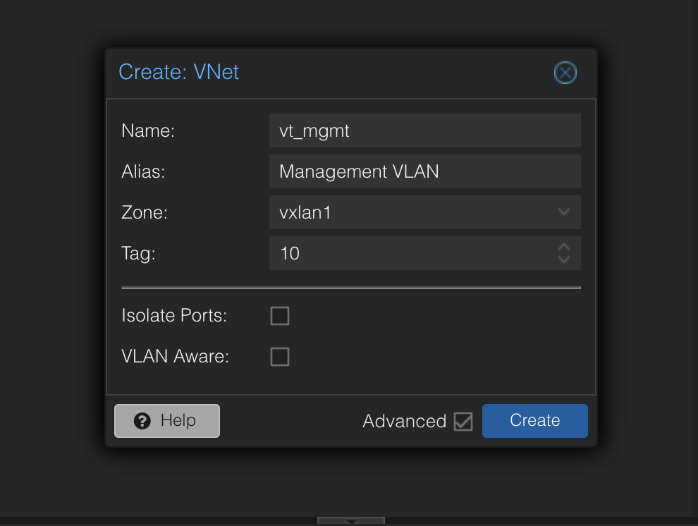 Example of a VTNet creation
After creating all the VTNets the result is something like this (Ignore the legacy VTNet, I will not remove it until the migration is fully done to keep the services up).
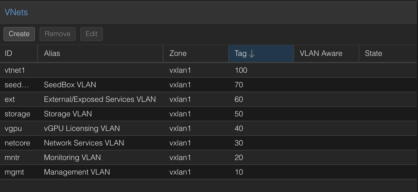 Naming is definitely not my best skill
Now, go to the general SDN view and click “apply” for the new config to spread to the nodes.
Setting up OPNSense
After creating the VTNets, next step is adding them to the OPNSense VM as vNICs (Virtual Network Adapters).
Two important settings in the Network Device creation dialog:
- VLAN Tag: We’ll leave this empty since we are relying on Proxmox Virtual Networks instead of using a trunk interface.
- Firewall: We’ll leave this unchecked since we’ll be managing the rules on the OPNSense VM.
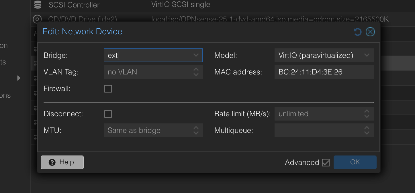
After adding a vNIC per VLAN, the result looks like this: 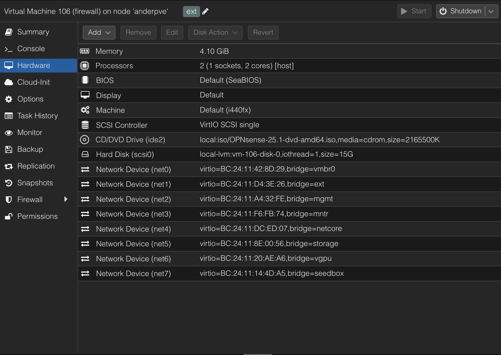 “net0” is the WAN adapter, it talks to the ISP router so VMs can reach the internet
Next up, we need to start the OPNSense VM and assign each interface their settings. In my case I’m going to use the following IP address scheme:
1
10.0.<TAG>.0/24
Since the “Ext” VTNet’s tag is 60, the interface’s IP address will be 10.0.60.1and VMs inside of the VLAN will be inside of the 10.0.60.2-10.0.60.254 range.
To do this, go to the OPNSense Web Panel and to the Assignments page of the Interfaces section on the Sidebar. Then, add the interfaces one by one.
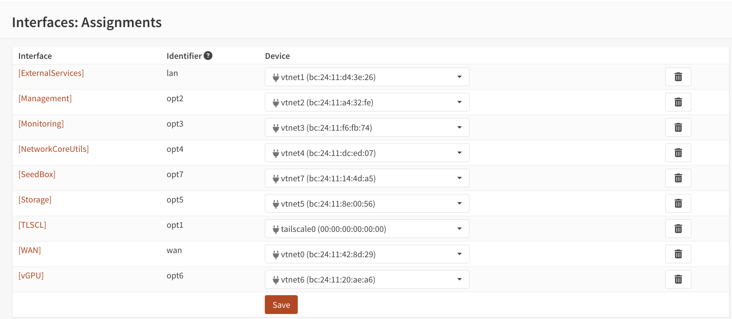 Newly created interfaces alongside the already present ones
These interfaces will now be visible on the sidebar. Last thing to do is to go in them and toggle the following:
- Enable interface: Ticked (pretty self-explaining)
- IPv4 Configuration Type: Static IPv4 (in case we want to use static assignment IPv4 which is what we will cover on this guide)
- IPv4 Address: IP address of the Interface according to the scheme I explained before. (Make sure to change
/32to/24or the network will only have the OPNSense interface)
To enable internet access for the VMs in the VLANs it is necessary to enable “Automatic outbound NAT rule generation” in the Firewall > NAT > Outbound NAT page.
Now that our Virtual Networks are set up, next step is to configure rules for each network.
Regulating the traffic (Putting the “Zero” in the Zero Trust)
What remains now is to open the right “holes” in the firewall so only the traffic that we desire can move in the networks.
General Rules
These rules only apply if you want the VMs to be able to access the internet.
OPNSense blocks traffic on networks by default. This means that you have to allow specific traffic to flow. Since the internet has lots of unknown IP addresses, we are going to allow VMs to connect to the internet by:
- Blocking all connections to local networks (RFC1918)
- Allowing all connections.
Since OPNSense rules work by evaluating the first matched rule starting from the top, the system will filter out requests to the local network but allow the rest of them.
To do this, we need to create a “Local_Network” alias that will cover all our local networks. In my case, I’ve used the RFC1918 specification. These aliases can be create at Firewall > Aliases.
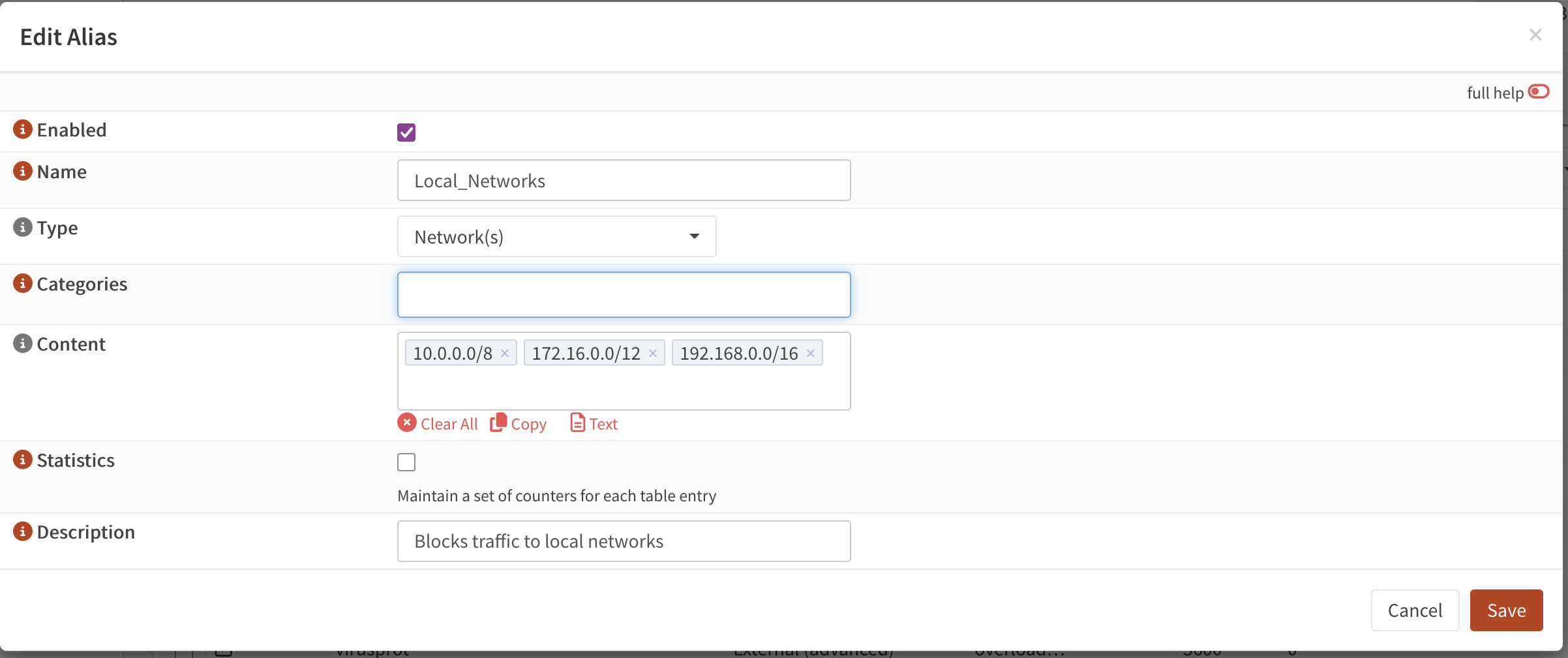 How the RFC1918 alias would look like
Now, we need to create the afforementioned rules in our Virtual Networks. To do this, go to Firewall > Rules and hit the orange ‘+’ button to create the rule.
| Name | Content |
|---|---|
| Description | Block Local Networks |
| Interface | <Interface that we want to apply it to> |
| Action | Block |
| Direction | In |
| Source | <The Interface’s network> |
| Destination | Local_Networks (Alias name) |
Setting the source to the interface’s network instead of “any” allows us to avoid IP spoofing attacks.
Leave the rest with the default values. Next up, we need to create our “allow all” rule so the VMs can access the internet.
For this, just use the default values (Action: Pass, Direction: In, Destination: Any) and set the source to the Interface’s network.
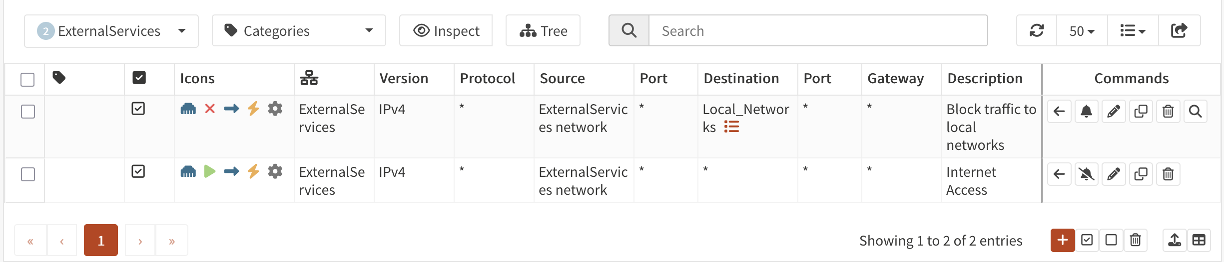 Example of the internet rules for the ExternalServices network
Now it’s time to poke holes per Virtual Networks.
Since OPNSense is a Stateful Firewall (it has memory), rules have only to be defined at the source VLAN.
For example VM1 (VLAN1) wants to establish connection with VM2 (VLAN2). If we allow that traffic from VLAN1, OPNSense will remember it and will also allow VM2 to answer to the petition without creating an outbound rule in VLAN2.
PD: I personally recommend aggregating host IP addresses into per-VLAN aliases. This way there is no need to modify rules, just the contents of the aliases. This is why in the images below aliases will be shown instead of IPs and ports.
External Services
This Virtual Network hosts services that are available on the open internet, and in consequence we really need think through which traffic we allow to flow. Two VMs are present in the VLAN: IPTV-Ext and Media-Ext.
- Both VMs need access to the DNS server in the NetCore VLAN (AdGuard host, port 53).
- Both VMs need access to the vGPU DLS to license their vGPUs (vGPU-DLS host, port 443).
Media-Extneeds access to the NFSv4 mount in the Storage VLAN soJellyfincan access the media files (Cockpit-LXC host, port 2049).Media-Extalso needs access to theSonarrandRadarrservices soJellyseerrcan work properly.
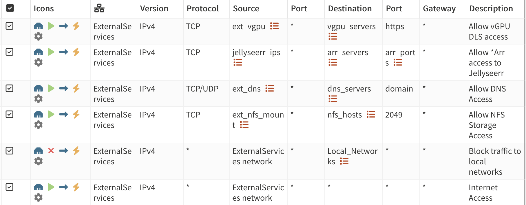 Aliases help keep it tidier
Seedbox
This Virtual Network hosts my Linux ISO downloading system (wink, wink). Since its main purpose is to index and download, it is another potential entrypoint for threat actors. As of now, it only hosts a single VM: Arr-Ext (I really should change its name since, thankfully, it’s not in the same network as the exposed services anymore).
- Needs access to the Jellyfin instance on the
Media-ExtsoSonarrandRadarrcan send webhooks to Jellyfin when new Linux ISOs are downloaded. - Needs access to the DNS server in the NetCore VLAN (AdGuard host, port 53).
- Needs access to the NFSv4 mount in the Storage VLAN so
Sonarr,RadarrandqBittorrentcan access the media files (Cockpit-LXC host, port 2049).
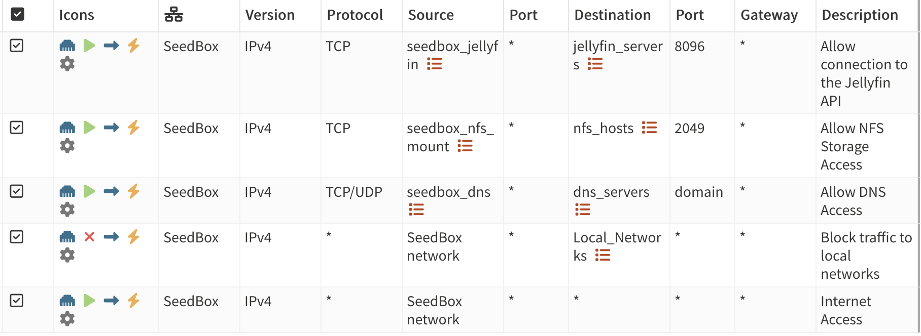 Fairly similar to the ExternalServices ones
Monitoring
This Virtual Network hosts both the Prometheus and Grafana instances that keep watch on the rest of the services of the network. As such, it needs access to every Virtual Network, but we will limit it so it only gets to the scraping endpoints that it needs.
- Both VMs need access to the DNS Server in the NetCore VLAN (AdGuard host, port 53).
- The
Prometheus LXCneeds access to the following scraping targets:IPTV-Ext: Ports9100(node-exporter),9292(Dispatcharr),8000(AceStream-Orchestrator).Media-Ext: Ports9100(node-exporter),8096(JellyFin),4533(Navidrome).Arr-Ext: Port9100(node-exporter).AdGuard-NetCore: Ports9100(node-exporter).Cockpit-LXC: Ports9100(node-exporter)
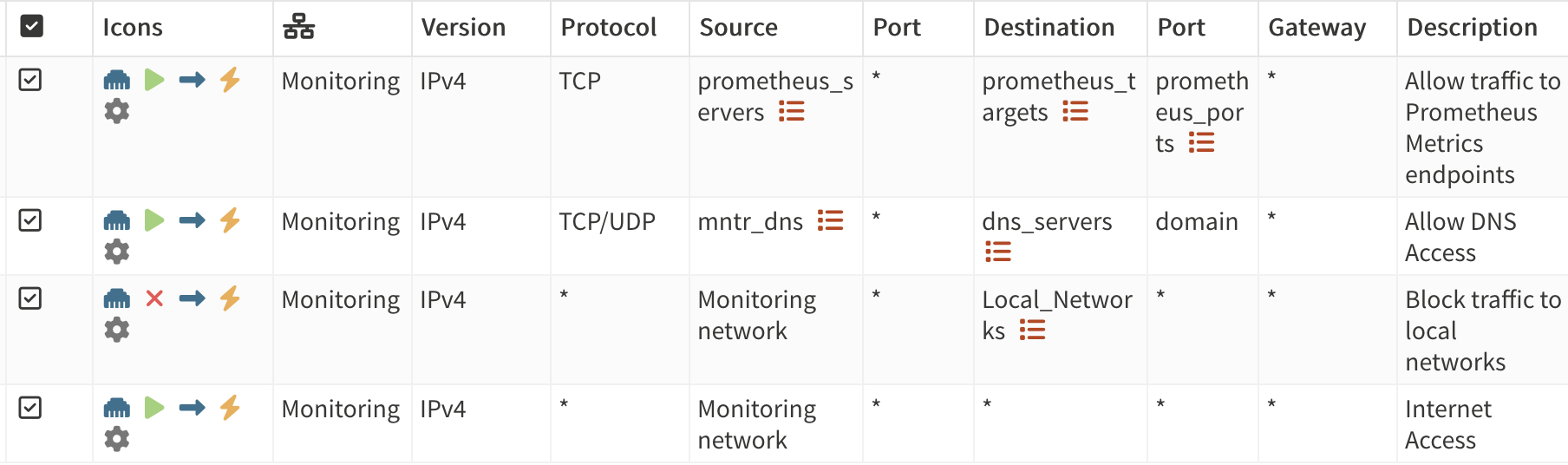
Network Core Utilities
Since this Virtual Network only includes the DNS server and thanks to the Statefulness of the OPNSense Firewall, we don’t need to create any rules (Except for the Internet Access ones) for this one.
vGPU and Storage VLANs
These Virtual Networks are mostly used by other nodes but they don’t really need access to them so they only need rules for the internet + DNS.
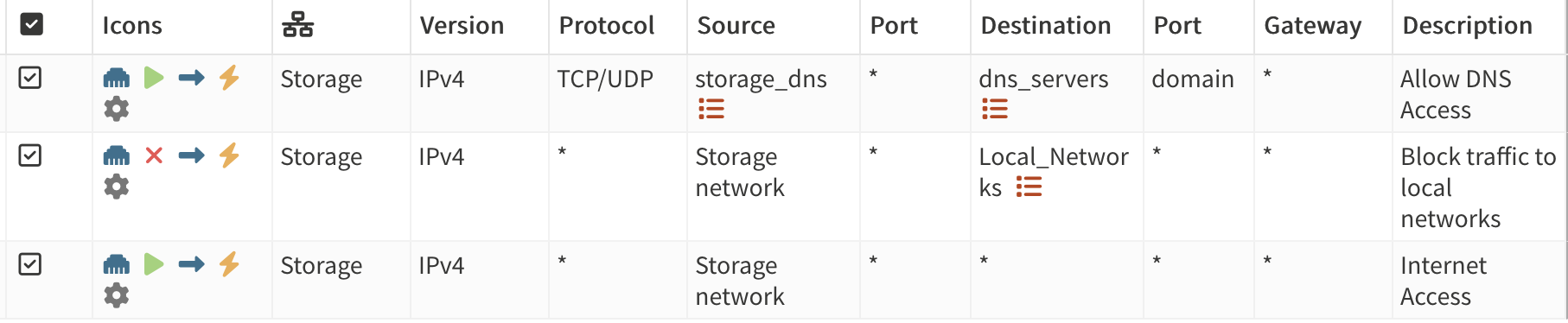 Rules for the Storage VLAN
Management
This Virtual Network is probably the most critical one: it hosts managing software such as Komodo (Docker management) and Terraform (Infrastructure as Code). These tools have plenty of power over other nodes of the Network, so we should protect it accordingly.
This means that tools inside of this virtual network will only be available via two endpoints:
- A Tailscale VPN connection to each node.
- The Proxmox Web Panel.
The LXC-Control needs access to the following:
anderpveandnaspve:8006(Proxmox API, for Terraform usage). If the panel is on your LAN (OPNSense’s WAN), make sure that on the WAN settings “Block private networks” is disabled.IPTV-Ext,Media-Ext,Arr-Ext,AdGuard-NetCore: Port8120(Komodo Periphery).
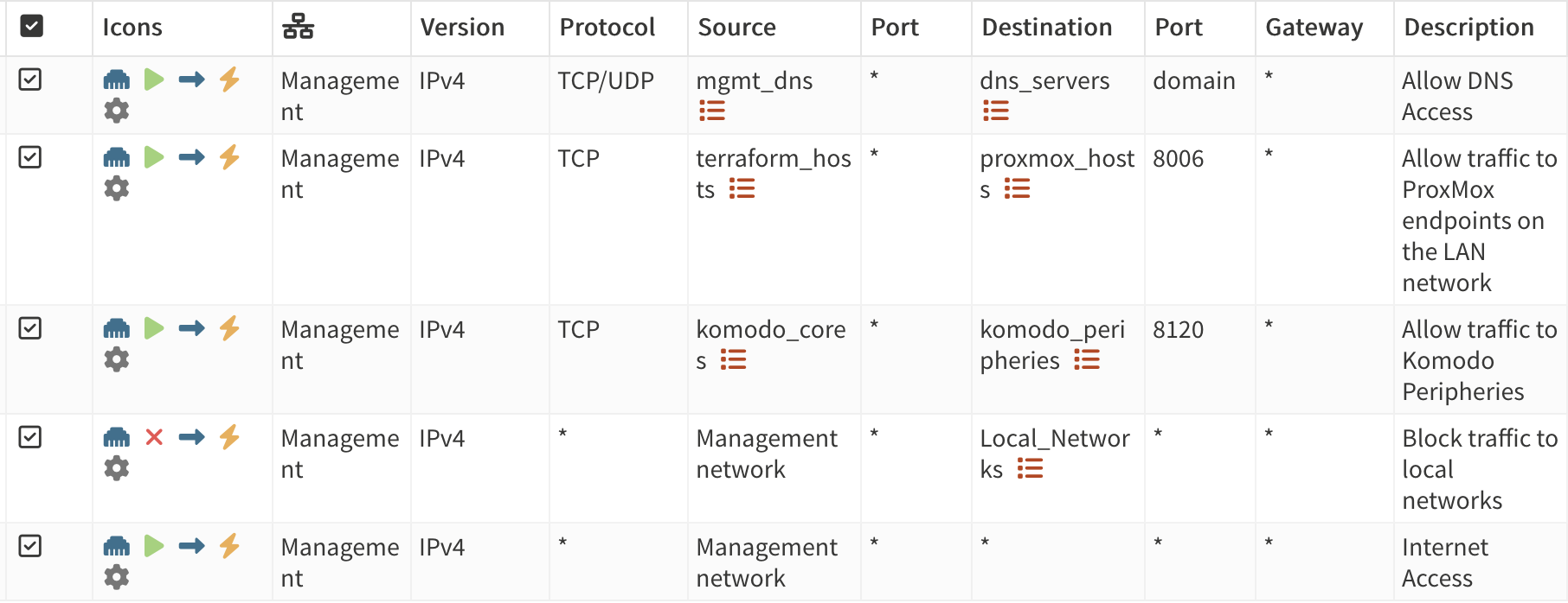
And with these last rules, we have finished reworking our network! (For now, of course)
Closing notes
The post has became a bit of a “ain’t reading allat” kind of article but I feel like my network is now on a way better state than it was before. Anyways, I hope you liked it and stay tuned for more!